Let's talk quantisation published: 27th February 2025
Digitalis a drug obtained from the dried leaves of the plant called Foxglove (Digitalis purpurea) is used in medicine to strengthen the contractions of the heart. It one of the most common drugs used to restore adequate circulation in patients with congestive heart failure. Ok what does that have to do with DSP or quantisation. You might have heard about digitisation where some form of analog data is converted to digital data which can be stored safely on a digital computer. Our computers are digital machines operating on digital data so why is the process of converting the analog data to be stored in computers called digitisation and not digitalisation? Well that's because the medical community has already taken up the term digitisation which refers to administrating the heart stimulant digitalis. So the people in the electronics field working on digital techniques had to settle with the term digitisation and not digitalisation even though the systems involved are digital.
Digit comes from Latin digitus which means finger, toe. When you count on our fingers each finger can represent one state up or down, you can't raise half of your number to count a value. We use a base 10 numeral system and for any such system with an integer base, the number of digits needed is the absolute value of the base. For example the decimal system which has a base 10 needs 10 digits (0 to 9) to represent any value in the system. Our current numeral system comes from Brahmi numerals. The numerals come from the Brahmi script a writing system from ancient India. One of the first usage of these numerals can be seen around the middle of the 3rd century BCE however the place value system developed later. This numeral system saw a spread over large areas during the Gupta period (early 4th century to the late 6th century). During the vedic period in the Indian subcontinent there was a need to work with very large numbers to understand various cosmological concepts like kálpa (the lifetime of the universe) which is said to be be 4,320,000,000 years and the "orbit of the heaven" said to be 18,712,069,200,000,000 yójana. A good understanding of geometry was needed to construct the fire altars for vedic rituals. Such a need for a numbers is what led to the development of robust numeral system in ancient India. They had names for increasing powers of 10
- daśa (दश) = 10 (101)
- śata (शत) = 100 (102)
- sahasra (सहस्र) = 1,000 (103)
- ayuta (अयुत) = 10,000 (104)
- niyuta (नियुत) = 100,000 (105)
- prayuta (प्रयुत) = 1,000,000 (106)
- arbuda (अर्बुद) = 10,000,000 (107)
- nyarbuda (न्यर्बुद) = 100,000,000 (108)
- samudra (समुद्र) = 1,000,000,000 (109)
- madhya (मध्य) = 10,000,000,000 (1010)
- anta (अन्त) = 100,000,000,000 (1011)
- parārdha (परार्ध) = 1,000,000,000,000 (1012)

The clever thing about this system was that you didn't have to count
the number of zeroes instead you could just use the word for the place
value and represent a number. For example a number like 56,789 can be
represented as
5 ayuta 6 sahasra 7 śata 8 daśa 9. In the
Āryabhaṭīya, written in 499 CE, Aryabhata used a fascinating place
value system where numbers were expressed using the Sanskrit alphabet.
Each letter represented a number, and its position determined its
value similar to how we use position today (ones, tens, hundreds,
etc.). What made this system particularly clever was that it could
represent very large numbers very concisely, which was essential for
his astronomical calculations. while Aryabhata didn't use a specific
symbol for zero, his mathematical methods clearly showed an
understanding of its role. For example, in his place value system, he
used the word "kha" (meaning "space" or "emptiness") to represent zero
in astronomical calculations.
The development of zero as we know it today was a gradual process that
spanned centuries and crossed multiple civilizations. The Babylonian
contribution (around 3000-2000 BCE) laid important groundwork. Their
base 60 system used place values, which was revolutionary for its
time. When they needed to represent an empty place (like we might
write 3004), they developed a "separation marker." Think of this like
leaving a space between numbers it showed something was missing there,
but it wasn't yet treated as a number itself. The Lokvibhāga
(लोकविभाग), written around 458 CE, marks a significant step forward.
This Jain astronomical text contained one of the earliest Indian
references to zero-like concepts. The Jain mathematicians were dealing
with extremely large numbers in their cosmological calculations, which
may have pushed them toward developing more sophisticated number
systems. Āryabhaṭa's approach to zero (around 499 CE) was particularly
interesting. While he didn't have a symbol for zero, his mathematical
procedures demonstrated an understanding of zero as a concept. When
working with his place value system, he used the word "kha" (खा) -
meaning "space" or "emptiness", which suggests he understood zero both
as a placeholder and as representing nothingness.
In 7th century CE Brahmagupta an Indian mathematician and
astronomer wrote Brahma-sphuta-siddhanta (Correctly Established
Doctrine of Brahma) which introduced first mathematical treatment of
zero. He defined zero as the result of subtracting a number by itself.
His word for zero śūnya same as the word for representing the empty
spot in the 9 digit place value system.
The modern format of the numerals called as Arabic numerals in the
West developed around 8th-9th century based on
the texts by al-Khwarizmi a Persian polymath
On the Calculation with Hindu Numerals
(ca. 825), and second Al-Kindi an Arab polymath four-volume work
On the Use of the Indian Numerals
(ca. 830).
Now we have a fully robust system of numbering which laid the
foundation for digital systems using binary digits to represent real
life data.
Ok so we have a numbering system with a base of 10 but our computers
use a numbering system with a base of 2. Why are we leaving out other
digits from our numbering system when it comes to computers? With base
2 what we are doing is storing one simple state of either "ON" or
"OFF" into logical circuits called flip flops. It is a circuit that
has two stable states that can store a binary digit (bit). We store
one bit using two transistors arranged in a cross coupled
configuration in the flip flop circuit. This creates a stable system
with two possible states: high or low voltage. It's like two switches
that are connected so that when one is on, it keeps the other off, and
vice versa. All transistors do is control the flow of the current and
either pass it or block it. If the output read is a passing current
that means the state is ON else it's OFF. If we have decimal based
computers each flip flop now has to represent 10 states. Since these
circuits work with voltage to represent their states in voltage we'll
need to divide the base voltage in 10 sections. Let's say the
electronic circuit in the computer works with 5V so with a decimal
based system we will divide the 5V into 10 distinct sections
approximately 0.5V apart. Each level would need incredibly precise
voltage control:
0 = 0.0V to 0.5V
1 = 0.5V to 1.0V
2 = 1.0V to 1.5V
and so on...
When we want to read the number stored in the flip flops we have to
provide the exact level of voltage as a reference to get the value
stored which is quite hard. Having a constant voltage of a fixed value
is not easy and precise, it will always have noise and fluctuation
built into it. If we're storing 3 (approximately 1.5V), and our
reference voltage drifts to 1.45V or 1.55V due to temperature changes
or component aging, we might misread the value as 2 or 4. Electrical
noise becomes a major problem because it could easily push our voltage
across the threshold between two decimal values. Also, with decimal
system we need more components to store a value since we have 10
possible digits to represent that value. In a decimal computer,
component degradation becomes a serious problem because we're relying
on precise voltage levels to represent different digits. Any higher
base than 2 creates a lot of engineering complexities as every
component in the computer needs to be more precise, more stable, and
more complex than its binary equivalent. The result would be:
- Much higher manufacturing costs
- Lower reliability Higher power consumption
- Larger physical size
- More points of potential failure
This is where binary system comes to rescue us. Binary circuits either
have a current or not. This can be represented as
1 and
0 respectively. This can also correspond
to true and
false which makes working with boolean
logic directly applicable to physical circuits. Think of the binary
system as a switch which is either ON or OFF, there is no intermediate
state. When reading the output in a binary system we do not have to
provide a constant reference voltage, all we have to check if the
output is ON or OFF. Ok, so we are storing 1 of 2 possible states in
each flip flop but how do we store for example number 5 in this
system? Using the place value system we can derive a binary
representation of the numbers to store. Let's first identify what
powers of 2 we'll need:
20 = 1 (fits into 5)
21 = 2 (fits into 5)
22 = 4 (fits into 5)
23 = 8 (too big)
So we'll need 3 bits to represent 5, since 22 is the
largest power of 2 that fits.
Now let's convert step by step starting with 5, we work from left to
right:
Can we subtract 4 (22)? Yes: 5 - 4 = 1 remaining, write 1.
Can we subtract 2 (21)? No: 1 < 2, write 0.
Can we subtract 1 (20)? Yes: 1 - 1 = 0 remaining, write 1.
Therefore, 5 in binary is 101.
We can verify this by adding up the place values:
1 in the fours place (22) = 4
0 in the twos place (21) = 0
1 in the ones place (20) = 1
Total: 4 + 0 + 1 = 5
So we can store number 5 using 3 bits so 3 flip flops that means this
solution uses less space compared to bases higher than 2. Now when we
read the output of the flip flop circuit we do not need a reference
voltage instead we just read the if the circuit is ON then assign 1 to
it and if it's OFF assign 0 to it. This makes the overall storage
solution easy to work with compared to systems with base greater than
2. This is why computers use just 2 digits 0 and 1 to store data. We
did have non binary computers before binary ones came along in form of
analog circuits but using analog circuits for computation is dangerous
as they are sensitive to noise. Binary circuits also get affected by
noise but not as much as analog ones. Even if there is noise in binary
circuits an ON is actually ON and not any other value (in this case
OFF).
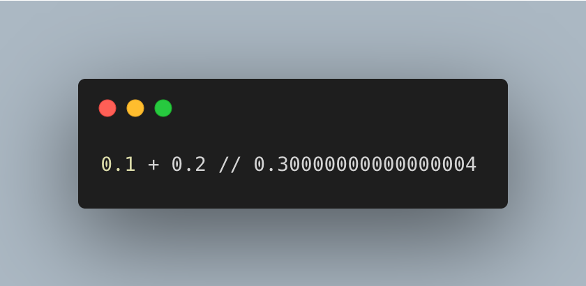
Computers are very good at storing and recalling numbers but unfortunately this process comes with its own errors. This is what happens when you add 0.1 and 0.2 together in Javascript. This is not a bug! I have seen a lot of comments online on this behavior where people claim Javascript is bad because look it cannot even do a summation the right way. But problem is not with Javascript, it's just how computers deal with floating point numbers using a binary system to store the number.

Computers have something called Arithmetic Login Unit (ALU) which is a math processor. To perform addition of two numbers the CPU will transfer 8 bytes to the ALU for the two numbers and additional bytes instructing it what to do with it. After a short time the computation result is returned back to the CPU containing the sum. New modern computers have now broken the mathematical functions into elementary binary operations that can be managed in the CPU itself reducing the overall execution time for the operation. The bit-ness of a processor refers to its ALU width, this is the width of the binary number that it can handle natively in a single operation. A 64 bit processor can operate directly on values which are 64 bits wide, in a single instruction. This happens because we have a fixed number of bits are allocated to store each number usually 8, 16, 32 or 64. To store number 5 we just need 3 bits but to store a large enough value we need more bits. For example for 8 bit computing system only 28 = 256 possible bit patterns are available so that variable can only take on 256 different values. This is a fundamental limitation of the system. What we can do differently is that how we represent this pattern of bits. The patterns themselves are just patterns: we get to decide what values they represent, as long as everyone using the system agrees on the interpretation. So let's say we interpret pattern represents 256 exponentially related numbers: 1, 10, 1000, 104, ..., 10255. Place value system shines again! Storing whole numbers like 5, 10, 15 is easy by translating them to their binary representation but real life data is rarely whole numbers. For example any application working with money needs to fractional values to represent a given amount like $50.87. So how do we store such fractional numbers using binary? Why binary numbers shine with their implementation is that there is no inherent meaning in a binary word. The meaning of an n-bit binary word depends entirely on its interpretation i.e. the mapping we choose to use for a binary word. Everyone using the system must understand this rule of the representing the pattern and the system can provide an algorithm or formula for converting between the represented value its corresponding bit pattern. The two most common techniques for this are Fixed point and Floating point.
Fixed Point
Yea what is fixed here? The "fixed" in fixed point refers to the decimal point. Fixed-point numbers are still stored in binary, they're just a particular way of interpreting those binary bits. In a fixed-point system, some bits represent the integer part and some bits represent the fractional part. This allows us to represent non-integer values while still using simple binary. The computer doesn't actually store a decimal point it's just a way of interpreting the bits. The programmer or system defines where the point is and all operations maintain this interpretation. These are of two types: signed and unsigned integers. High level programs such as C usually allocate 16 bits to store each integer. This gives us 216 = 65,535 different bit patterns which are assigned to the numbers 0 to 55535. This is called unsigned integer and in unsigned integer format, we simply count up from 0. It's like having a counter that can only go forward, great for counting things where negative numbers aren't needed. With 16 bits, we can count from 0 to 65,535, which is why this format is used when we know our numbers will always be positive. But what do we do when we want to store let's say the number 65536? To store 65536, we need an extra 17th bit. But since computers typically work with standard sizes (8, 16, 32, or 64 bits), we would typically use 32 bits to store this number. This is why programming languages often offer different integer types: 16-bit integers (can store 0 to 65,535), 32-bit integers (can store 0 to 4,294,967,295), 64-bit integers (can store even larger numbers).
Ok what about negative numbers then? We represent negative numbers using a technique called binary offset. Here the decimal values are shifted to allow negative numbers. The decimal values are offset by 7 for a 4 bit integer. This results in 16 bit representation corresponding to the numbers -7 through 8. From the 16 bits we assign one bit to the sign of the number which leaves us with 15 bit patterns and hence a range of -32,767 and 32,768. The offset value is not standardised so you might see other offsets in different processors.
There is another way to represent negative numbers called sign and magnitude. In this technique the far left bit of the pattern is called the sign bit which is made 0 for positive numbers and 1 for negative numbers. The remaining bits are used to represent the absolute value of the number.
Using sign and magnitude is simpler but it wastes one bit pattern as
there are two representations for zero: 1000 (negative zero) and 0000
(positive zero). Since the left most bit is reserved for the sign we
get 15 possible bit patterns which gives us 215 values from
-32,767 to 32,767.
These encoding schemes seem easy to for us to understand logically but
implementing this in the hardware is a complicated task as it requires
meticulous handling of data representation, scaling, and precision.
When we perform an operation like x = y + z some hardware engineer had
to figure out how to make the bit pattern representing y combine with
bit pattern representing z to get the bit pattern representing summed
x.
Two's complement is such a technique that simplifies the
implementation of doing arithmetic operations on binary words. We
follow these steps to get a two's complement of any number:
- Take the absolute value of a decimal number eg. 5
- Convert it to binary: 0101
- Flip each bit in the pattern: 1010
- Add 1 to the resulting pattern: 1011
Using 16 bit two's complement can represent numbers from -32,768 to 32,767 as the left most bit is used to represent the sign of the number.
Floating Point
Ok but there's some issues with fixed point arithmetic. With a 32-bit fixed point number where 16 bits are for the fraction, you can only represent values from approximately -32,768 to +32,767 with fractional precision of about 0.0000152. With fixed point, you must decide in advance how to allocate bits between the integer and fractional parts. If you need more range, you sacrifice precision and vice versa. Fixed point arithmetic easily results in overflow (when numbers get too large) or underflow (when numbers get too small) without built-in mechanisms to handle these conditions. So we have another technique called Floating point arithmetic which helps resolve all the issues mentioned. As you might have guessed from the name the decimal point in floating point is not fixed but rather dynamic. It is a bit complicated as it uses scientific notation to represent numbers but offers a lot more benefits as compared to fixed point. A floating point number has three parts:
- Sign bit: Determines if the number is positive (0) or negative (1)
- Exponent: Controls the magnitude (how large or small the number is)
- Mantissa: Holds the significant digits of the number
For instance, 6.345 x 10⁵ where 6.345 is the mantissa and 5 is the exponent. Scientific notation is exceptional at representing very large and very small numbers. The distance from earth to Andromeda galaxy is 23,652,500,000,000,000,000,000 meters and that in scientific notation is 2.365 x 10²² meters. Planck length (smallest meaningful measurement of distance) is 0.0000000000000000000000000000000000016 meters but in scientific notation its 1.6 x 10⁻³⁵ meters. So you can see how easy it is to represent numbers using the scientific notation. Numbers represented in this notation are normalised which means there is only one single nonzero digit left of the decimal point and is achieved by adjusting the exponent. Also, floating point works with base 2 instead of base 10 as used by the scientific notation. Since the only nonzero number in base 2 is 1 the leading digit in the mantissa will always be 1 and so does not need to be stored. This allows the number to have an additional 1 bit precision. IEEE 754 is the most widely used standard for representing floating point numbers in computers. Created in 1985 and revised in 2008 and 2019, it defines how computers store and manipulate decimal values. This is the standard everyone agrees to when using computers and hardware of any kind for mathematical operations.
Oof! A lot of theory! I almost forgot why was I even talking about fixed and floating point numbers. AHH yes! the peculiar mathematics of programming languages. So why does adding 0.1 and 0.2 result in 0.30000000000000004? When we write 0.1 or 0.2 in decimal, these are simple fractions 1/10 and 2/10. However, computers store numbers in binary base 2 and some decimal fractions that are simple in base 10 become infinitely repeating fractions in base 2. 0.1 = 0.0001100110011... in binary (infinitely repeating) and 0.2 = 0.00110011001100... in binary (infinitely repeating). There is no finite binary representation of 0.1 or 0.2. The computer has to round somewhere creating a tiny error which is called a round off error. Since computers have limited precision, they can only store an approximation of these values. When we add these approximations together we get another approximation that's slightly off from the exact 0.3 value. It's similar to how 1/3 can't be exactly represented in decimal (0.333333...) so if you add 1/3 + 1/3 + 1/3 in decimal with limited precision you might get 0.999999... instead of exactly 1. If we randomly pick a 32-bit floating point number (which has 24 bits of precision including the implicit leading bit) the gap next to that number is approximately 2-24 to 2-23 times the number itself, which is roughly one part in 10 million. This is a key concept when dealing with floating point notation large numbers have large gaps while small numbers have small gaps between them.
When performing mathematical operations on floating point numbers the round off errors cause the value to gradually drift away from the initial value. The drift can take one of two forms depending on how the errors add together. If the round off errors are randomly positive and negative the value will randomly increase and decrease but fi the errors are mainly on the same sign the value will drift away much more rapidly and uniformly. Additive errors tend to simply accumulate while random errors tend to cancel each other. Since we can't control which way the round off error will go expect that for every single precision (32-bit) number we will have an error of about one part in forty million multiplied by the number of operations it has been through while a double precision (64-bit) number will have an error of about one part in forty quadrillion multiplied by the number of operations. The maximum relative error ε is: ε = 2-p where p is the number of bits in the mantissa (including the implicit leading bit).
OKAY! Let's finally talk quantisation now! Let me define quantisation for you: it is the process of converting a sample measurement (voltage in this case) to a fixed binary representation. We take a analog value and store it in our digital computers using a fixed binary representation mainly using floating point notation. What does that process look like?

The input is a voltage signal that varies over time which is then fed into a sample and hold circuit. What is a sample and hold circuit doing here? Firstly, the analog input is constantly changing over time and to digitise the signal it needs to held at a constant voltage else it would cause errors in the digital output. Secondly, the ADC needs a finite amount of time to perform the conversion and the S/H circuit holds the instantaneous value of the signal giving enough time to sample it. An external clock drives the S/H circuit based on the sampling frequency and updates during the rising or the falling edge depending on how the clock is configured. Notice an interesting behavior in the sampling here, when the S/H is in the hold phase we are ignoring the changes in the input signal. This transforms the independent variable (time in this case) to discrete from continuous. Let's sample an audio signal with a 12-bit ADC and assume the voltage range is between 0V and 4.095V. So both these voltages 2.56000V and 2.56001V wil be converted to 2560 which raises an important point: quantisation converts the dependent variable (voltage in this case) from continuous to discrete.
When we are quantising an analog voltage signal like an audio signal we are essentially rounding each sample top the nearest bit available. The spacing between these levels is called 1 LSB (Least Significant Bit). When an analog value falls exactly halfway between two quantization levels, it gets rounded to one of them. The maximum distance between the original value and the quantized value is therefore half the distance between levels which is ±1/2 LSB.
If you notice the quantisation error graph you'll see that it looks like random noise. This raises an important point quantisation results in nothing more than addition of a specific amount of random noise to the signal. Since quantisation error is a random noise, the number of bits determine the precision of the data. This looks good until we come across a signal with same values for many consecutive samples. In the chart E the analog signal is fluctuating around 3002 millivolts with a peak of 3004 millivolts. The output of this analog signal in the digital sample will be stuck to the same value for many samples in a row even though the analog signal may eb changing up to ±1/2LSB. This adds distortion to the digital signal. For signals with very low amplitude the quantisation error becomes highly correlated with the original signal but with distortion built in.
So how can we prevent this? Dithering is a technique for improving the digitisation of the such slowly varying signals. What we do is add a small amount of random noise to the analog signal before quantisation. Hmmm noise you say? Yes! noise. Let's say the input signal is a constant analog voltage of 3.0001 volts which is one tenth of the way between the digital levels 3000 and 3001. If we were to take 10,000 samples of such a signal we'd end up with all identical samples. The noise added to the analog signal causes the adjacent signals to sometimes round up and sometimes round down rather than rounding in the same direction. It is quite strange yes but adding noise provides more information.
Now compare the chart E and G. Chart E has no dithering noise added to
it and the digital signal is pretty flat. The digital signal generated
from analog signal mixed with dithering noise preserves more
information from the analog signal. The noise in the signal depends on
the bit depth used to do the quantisation. The effect of noise can be
minimised by using higher bit depth. I hope this gives you a good
insight into what quantisation is and how due to a limited bit depth
(32, 64-bit) our digitised signal always contains error.
In later articles I will be talking about Convolution and Fourier
Transform which we will be using to process our audio signals.