Synthesising a kick drum sound
A brief history of drums
Drums play an important role in the rhythmic structure of almost every genre of music. From kick drums, bass drums, snare drums, etc. in the Western music to tabla, dhol, mridangam, dholak, etc. in the Indian music to the Persian zerbaghali to tanggu in China, drums have existed in all major civilisations in one form or the other for musical and non-musical purposes. First earliest evidence of drums comes from the idiophones (produce sound via the vibration of the entire instrument) made from mammoth bones found in present day Belgium dating back to 70,000BCE. The earliest archaeological evidence comes from China dating back to the Neolithic period around 5500BCE where drums were made out of hollow wood logs and covered with alligator skin. There is evidence of drums around the same time in Mesopotamia where they played an important role in the religious affairs of the Sumerians. The first metal drum dates back to Bronze age in present day Vietnam. Drums can be seen in the sculptural artwork of Greece and Rome indicating the use of the instrument for cultural and military endeavors. The history of drums to Europe through Greece trace their roots to Danbara from ancient Persia imported with the name Tympanon. It was also know as Tympanum in the Roman culture. In Europe Tabor a portable snare drum played either with one hand or wit two drumsticks emerged as the prominent percussion instrument. The Renaissance witnessed further development in percussion particularly in military applications. In European armies drum became the instrument for issuing commands, coordinating movements, etc. The industrial revolution brought a new wave of changes in the drums with new materials such as metals and synthetic skins. William Ludwig's invention of base drum pedal in 1909 revolutionised percussive performance. This paved the way for the development of the modern drum kit which became popular across various music genres such as Jazz, rock, etc.
Physics of percussion
The word percussion comes from the Latin word percussionem, which means “a striking, a blow". A percussion instrument is one that produces a sound when a part of it is struck. Here are four primary percussion groups
- Membranophones(commonly called drums): these produce the sound through a membrane/skin. eg. timpani, snare drum, bass drum, tabla, etc.
- Idiophones: instruments that create sound through the vibration of the entire body. e.g xylophones, glockenspiels, cymbals, hi-hats, gongs, etc. Material and construction determine the pitch and timbre.
- Aerophones (air percussion): instruments that produce sound through air vibration. eg. whistles, sirens, some types of organ pipes, wind instrument family, etc.
- Chordophones (string percussion): instruments that produce sound through struck strings. eg. primarily the piano family
You can further subdivide the membranophones and idiophones based on pitched and un-pitched sounds. pitched membranophones include tabla, timpani, talking drum from West Africa, etc. unoitched membranophones include snare drum, bass drum, tom-toms, etc.
Pitched idiophones include bells, xylophones, glockenspiel, etc.
unpitched idiophones include cymbals, hi-hats, triangle, wood
blocks, tambourine, etc.
Further subdivision is possible based on the type of construction of
the instrument.
- single headed instruments have a single membrane with air pressure on each side. eg. cymbals, toms and conga.
- double headed have two membranes with air trapped between the two membranes. eg. snare drum, bass drum, etc.
Various such subdivisions are possible for percussion instruments.
Consider this a vibrating string has one dimension: its length, it can only vibrate in one dimension across the length of the string. Other properties such as its density and tension affect it but in a 3D world it has only one primary dimension. Now compare this with a drum. It has a circular (typically) membrane that is stretched with tension at all points. Unlike a string a drum has 2 dimensions: both along the surface and perpendicular to that surface. You can measure how long and wide the surface is. A membrane can vibrate in multiple modes because it is two dimensional and each point can vibrate in different ways depending on the combination of its radial and tangential displacements. In terms of a vibrating membrane modes of vibration are the distinct patterns of deformation that occur at different frequencies. These patterns arise due to the standing waves across the surface of the membrane. Each mode has a unique spatial pattern and the number of nodes points where the displacement is zero and antinodes points where displacement is at maximum varies.
Let's say you hit the drum exactly in the center. It will vibrate up and down just like the fundamental frequency of a vibrating string called w01 mode of the membrane. The modes of vibration can be described as wm,n where m is the radial mode and n is the circular mode. In radial mode the vibration patterns consist of lines running outwards from the center to the rim along the diameter lines. The membrane is divided into wedge-shaped sections by these nodal lines, with adjacent sections moving in opposite directions. The number of nodal diameters defines the mode number, eg. w3,0.
In circular mode of vibration the displacement patterns form concentric circles around the radius. The membrane moves up and down in rings, with adjacent rings moving in opposite directions. These modes are characterized by the number of nodal circles (where there is no movement) between the center and the edge of the membrane. In the diagram below the shaded part moves up and unshaded part moves down, eg. w0,2.
When you strike membrane in the center it vibrates in the fundamental mode which is w0,1. In this mode the membrane moves up and down like a string vibrating at its fundamental frequency. Maximum displacement occurs at the center of the membrane and least displacement at places it is fixed near the rim. Since it's a membrane you can't put a finger in the center to generate only second harmonics. Now placing your finger half the way from center of the drum will land you on an incorrect position, remember it's a membrane. The zero points of a string with the relation 1/integer does not work for membranes. Using something called a Bessel function you can compute the zero points of a membrane and the first zero point or the first overtone is 42.6% of the distance from the center to the rim. So at about 42.6% of the way from the center to the rim, you hit the first zero point a point where there's no displacement. The frequency of the vibrating mode in this way called the w02 mode is 2.296 times the fundamental.
For the next harmonic the mode of vibration is w03.
Some modes of vibration like w1,1, w1,2, w1,3, w3,1, w4,1
This is how the modes of vibration look like in 3D for a membrane
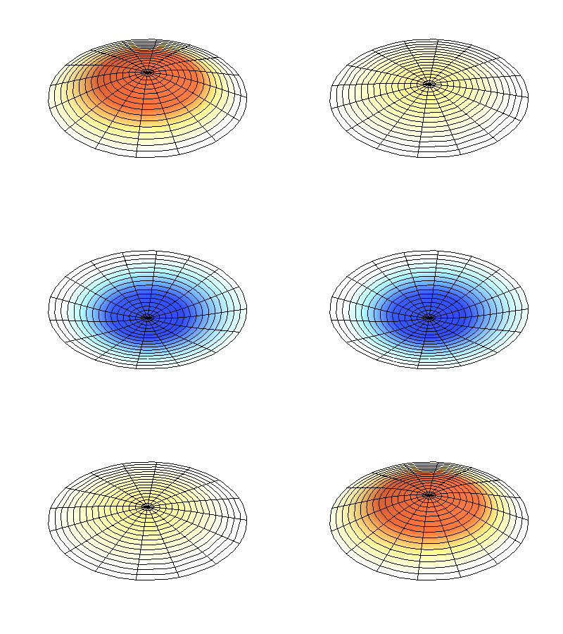
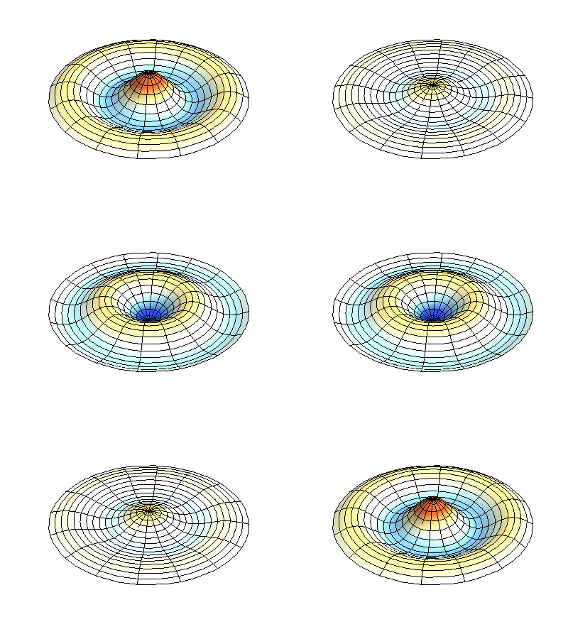
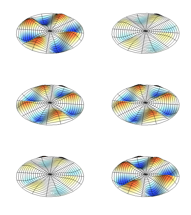
Compared to a vibrating string the frequencies are not harmonically related to the fundamental instead they are enharmonic with respect to the fundamental frequency. Just like a vibrating string the membrane of a drum vibrates in number of its different modes simultaneously. They all will have different amplitudes and all decay at different rates. This makes the sound from a drum so complex and almost impossible to emulate using different waves from a simple harmonic oscillator. The membrane generates more harmonics and they are clustered in an uneven manner unlike the regular spaced overtones in the simple harmonic oscillator. This makes the drum sound atonal and stops us from perceiving a particular pitch and tone of the sound. Also, no matter how carefully you adjust the membrane it will always have slight variations in the tightness and tension across the surface! In an ideal linear system the frequency of the vibration would stay the same regardless of how hard you hit the drum but drums don't behave this way. When you hit a drum harder they produce a higher pitch. This means the fundamental frequency increases with the large displacement of the drumhead when you strike a drum harder. The fundamental frequency is related to the displacement of the membrane.
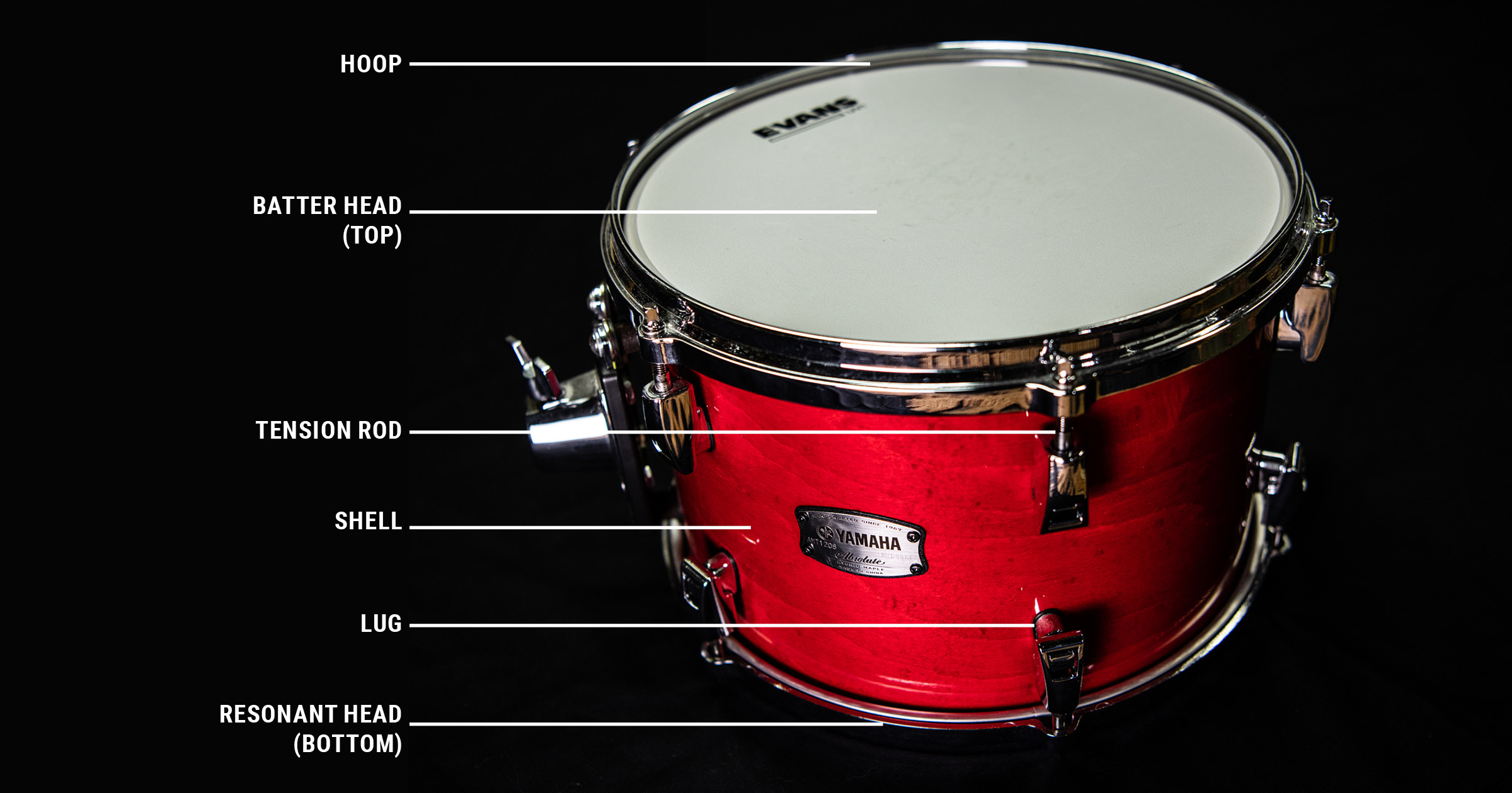
The head that you strike is called the drum head or the batter head and the other is resonating or carry head. With the air trapped inside 2 membranes a drum bass has 3 coupled resonators.
A modern kick drum is not exactly like a bass drum. A bass drum is something you might see in a marching band being played by hands while a kick drum is meant to be played by "foot" using a kick pedal (might as well call it a foot drum). All kick drums are bass drums but not all bass drums are kick drums. A kick drum which evolved from a bass drum is modified specifically for modern music. We will be synthesising a kick drum and not a bass drum since a kick drum has more punch which I really like in my tracks. A kick drum does not have 2 complete membranes instead there is a hole in the carry head which has several purposes like:
- Sound control: The hole can be used to place dampening materials inside the drum to control the overtones and reduce the sustain creating more punchy sound.
- Microphone placement: Mics can be put in the hole to record the sounds better in live performances.
- Tonal character: The hole changes the acoustics of the drum by releasing the air pressure more quickly.
Having a hole in the membrane surprisingly does not affect the frequencies of the sound much. The frequencies of a kick drum have a harmonic spectrum at lower frequencies with a large number of densely packed enharmonic frequencies at mid and higher frequencies.
After this there are 2 more components that we need to take into account while synthesising the sound: the frequency shift and the 'click' sound of the beater head. The carry head of the kick drum has more freedom to vibrate because of the hole in the drum. But what causes the pitch change? Remember, the pitch is entirely dependent on the tension of the membrane.
Let's say you have 22 inch membrane drum and you hit it in the center. The energy from the hit will displace the center by 1/16th of an inch which in turn increases the tension of the membrane. This increase in tension is proportional to the square of the displacement. Since the pitch is determined by the tension this increases the pitch of the modes. This means the pitch of every mode will be higher at the start when there is maximum displacement and will drop as the energy dissipates from the membrane. The pitch of the drum can shift by a couple of semitones from start to finish and we need consider this in our synthesis for a more natural drum sound.
The click comes from the beater hitting the drumhead which sends a shockwave across the membrane of the drum which travel outwards from the point of the impact. Due to this several high frequency inharmonic partials are formed for a very less amount of time since high frequencies dampen quickly due to the material of the membrane. The stiffness and mass of both the beater and the impact point of the drumhead determine which higher frequencies get more excited.
Now that we have the frequency content of the sound let's understand the amplitude levels of the sound. The amplitude at the lower modes are the highest hence loudest and the amplitude decreases rapidly at higher modes of vibration producing higher frequency components. When a percussive instrument is struck, you introduce a high level of energy into the system and this initial high energy produces a high amplitude. The attack is instant and injects maximum energy in zero time. So the amplitude is loudest at this point. As soon as all the energy is transferred into the system, it starts to vibrate and starts to lose that energy. The energy loss is proportional to what the current energy in the system is. This is an exponential decay. A vibrating membrane in this case loses energy because of damping through friction, air resistance, radiating sound, etc. The loss of energy is fractional of what current energy is and not an absolute value. A constant ratio. Energy and amplitude both decay exponentially but at different rates since energy ∝ amplitude2 which means energy decays twice as fast as amplitude.
Now that we have know the frequency content and the amplitude levels of a bass drum we can think about synthesising the basic sound. As we just saw, the physics of the bass drum sound is quite complex. There are 3 resonators in the system which produce multiple frequencies for a mode. The sound is "unpitched" for a bass drum because of these inharmonic frequencies. A pitched sound has a solid high energy fundamental frequency which our brain uses to recognise the pitch. Another factor for the brain to recognise pitch is the harmonic relationship of the frequencies. For a pitched sound all the frequencies are related to the fundamental frequency with the relationship n * fundamental frequency which is an integer ratio. This makes the harmonics of the sound to be separated evenly with each other. For a pitched sound of 50Hz, the fundamental is 50Hz which is the first harmonic, the second harmonic is 2 * 50 = 100Hz, the third harmonic is 3 * 50 = 150Hz, so on and so forth until infinity. However, a bass drum's acoustics does not behave like that. For a drum vibrating, something called Bessel function determines the harmonic relationship with the fundamental. So if the fundamental is 50Hz the first harmonic is 1 * 50 = 50Hz, the second harmonic is 1.59 * 50 = 79.5Hz, the third harmonic is 2.14 * 50 = 107Hz, the fourth harmonic is 2.30 * 50 = 115Hz. So each harmonic is in a non-integer relationship with the fundamental. Since the harmonics are not placed evenly in the spectrum our brains can't really put a pitch on the sound. This causes bass drums to not have a stable pitch. However, what matters more for a bass drum is the timbre and not the pitch.
So, now the question is how do we synthesis these complex modes? The answer is we don't! Sound synthesis targets perceptual goals and not the acoustic goals. The aim is not to reproduce the physical phenomena but reproduce the perceptual effects. A bass drum when struck generates high frequency inharmonic partials which die out pretty quickly. The whole process is so quick that our brains can't even discern a pitch from that sound. The higher mode inharmonic partials die out in tens of milliseconds and settle into the fundamental. Our auditory cortex takes somewhere around 200-300ms to fully process an incoming sound and discern the pitch of the sound. Hence, a bass drum has this tight punch like *thwack* and then a simple body sonically. Most of the energy is around the fundamental which rings for hundred of milliseconds one the beater hits the membrane.
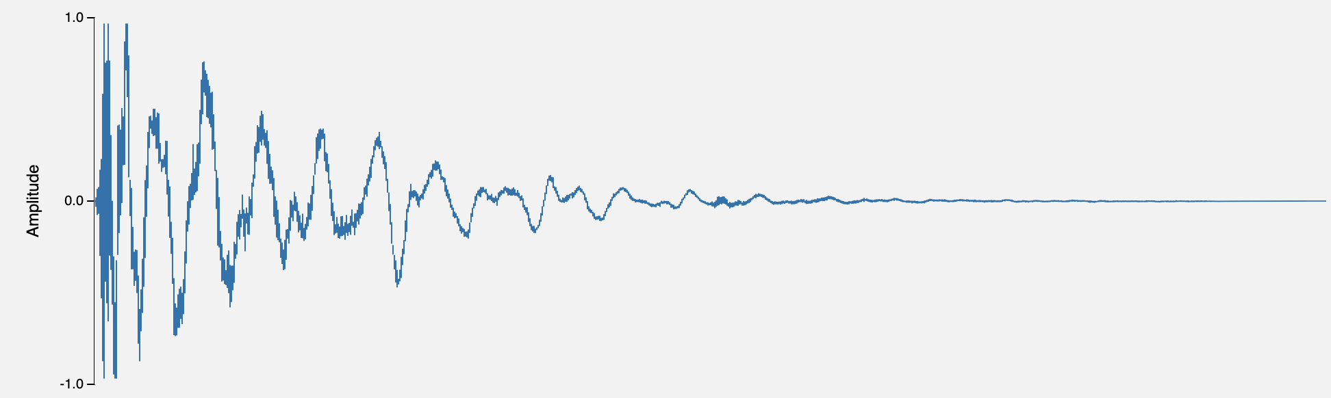
Let's look at the waveform. This is taken from a recording of a bass drum. Notice the spacing between the wave cycles at the start. That's a high pitched sound and hence the cycles are so close. This is the initial transient of the kick which sits at a really high pitch when the beater hits the membrane. The initial transient is so tightly packed that it almost looks like noise and slowly the spacing starts to increase between each cycle and as we discussed earlier now you can see that the higher inharmonic partials introduced in the membrane die out quick and slowly settle into the actual fundamental of the tone. Now let's look at the amplitude, the volume. The waveform is tallest at the start and slowly starts to decrease in height until it dies completely. This the exponentially decaying amplitude of the bass drum. The volume follows the decaying path of the energy introduced in the membrane. Energy and hence the amplitude decays exponentially. So to synthesise the sound the two things we need to model is the pitch (frequency) and volume (amplitude) decaying exponentially. Let's model the two behaviours on a chart and see what that looks like.
Let's start with the pitch. This is what an exponentially decaying pitch looks like if we plot the pitch against time. The membrane has a vibrational fundamental mode where it resonates strongly and has the highest level of energy. The beater hitting the membrane instantly transfers a a big amount of energy into the higher inharmonic partials of the vibrational modes for the first few milliseconds yet the fundamental frequency still has the highest energy. This makes the pitch of the tone start at a high frequency and as the energy dissipates what you hear is the fundamental frequency of the tone. So when synthesising the drum sound we will start with a high pitch which then slowly exponentially settles to its fundamental. The pitch shift for the drum at the start is around 2-3 semitones so that's the amount of shift we need to introduce while synthesising the sound. In this graph I have exaggerated the pitch shift just to draw the chart because 2-3 semitones would not show up properly on the graph.
Looking at the volume graph you can see the same exponential relationship as the pitch. The sound starts at a high volume and slowly decays into silence. The amplitude starts at its maximum and then starts to decrease as the energy dissipates away. Drawing the waveform here also show how the pitch is high at the start and then slowly settles down to its fundamental.
Synthesising a kick drum
Now that we have modeled the frequency and the amplitude of the sound, how do we synthesis it? So far I have tried two different methods on my modular rig trying to find a workflow for a punchy kick drum. For the two workflows this is what we need:
- Resonant filters
- Voltage controlled amplifiers
- Low pass gate (optional)
- A noise source
- Mixer
- A sequencer to trigger the sound
- Some utility modules that provide overdrive, saturation, distortion, clipping, etc.
You'll notice there's no oscillators in this list since in sound synthesis an oscillator is the primary source of sound but here I have chosen not to use an oscillator since I have only one oscillator which I want to keep for making basslines for my tracks. I'll explain why we can skip oscillators in this workflow and just stick to filters but instead of using filters oscillators can also be used in the two workflows. These are the two workflows that I use for kicks:
- Self damping pinged filter
- Self oscillating filter
Why filters? To be specific, we are using resonant filters. Resonant filters start to resonate at their cutoff frequency when their resonance all the way up.
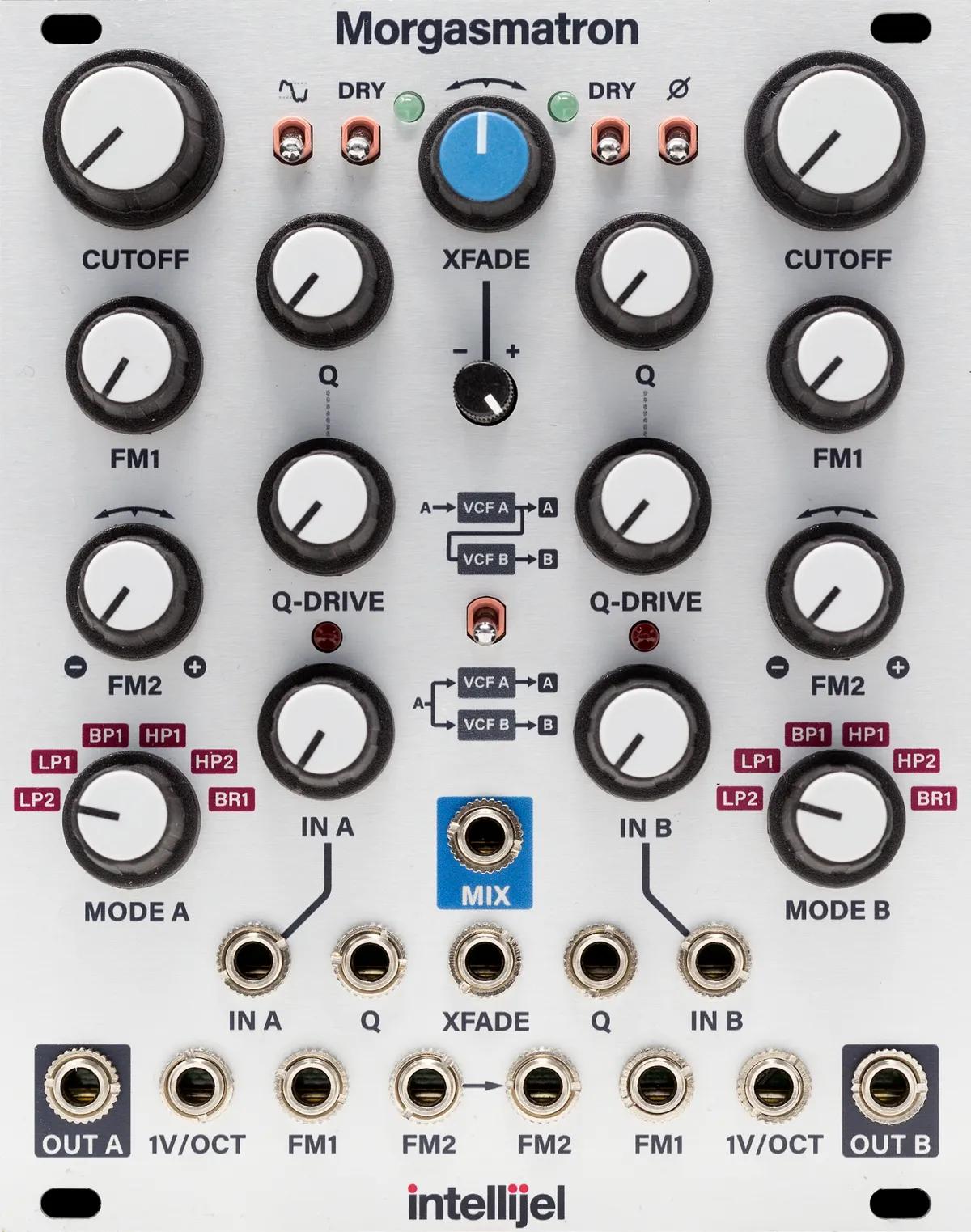
This is the filter I am using as a source of sound for the kicks I synthesise. Ok, so why use self oscillating or self damping resonant filters? The sound of a bass drum is quite simple in terms of harmonics. There is one fundamental which has the highest energy and some high frequency inharmonic partials in the transient but the fundamental tone is where most of the energy is concentrated. A self oscillating filter gives us a sine wave whose fundamental is determined by the cutoff frequency. If I keep the cutoff frequency at 50Hz and crank the resonance all the way up the filter outputs a sine wave at 50Hz at its output without needing to patch an input to the filter. This sine wave of 50Hz is where most of the energy resides which works well for us since it simulates the energy density of a bass drum. You can get this sine wave from an oscillator too but like I mentioned I have only oscillator and two different filters (one analog and the other digital) so I chose the filter as my primary sound source. Another good thing about the Morgasmatron is that it has a Q-Drive built into it which overdrives the resonance when it's turned all the way up. It has no effect if the resonance is anything less than 100%. So I don't need a separate overdrive module to add additional harmonics to the sound.
Now let's understand each of the workflows.
Self damping pinged filter
What's a self damping filter? To make a filter self resonate you turn up its resonance all the way and this pushes the filter to self oscillate at the cutoff frequency. This gives you an oscillator which is continuously emitting a sine wave. Every sound that we hear has a start and an end but an oscillator is constantly screaming and putting out energy. So, we need to gate the output of the oscillator and only open the gate when we want the sound to be produced. We do this gating using VCAs. We patch the oscillator to the VCA and send a control voltage to open the gate and emit the sound and once the control voltage drops the gate closes and the sound goes silent. However, if we use a resonant filter as a self damping sound source then the sound decays into silence by itself. This is actually the technique used by Roland's 808 kick drum sound. In an R&D for a drum synthesiser their aim was to keep the cost of the machine less than $1000 hence they chose this technique as it uses less components than the traditional way of synthesis at that time. The same reason I used this technique as my setup is still small. If I chose to synthesise my own kicks live then I won't have enough components left to patch other sounds in my mix. Ok, why not sample the kick? That will make the other components free for doing other stuff. I do have a fantastic sampler but don't have enough space in my rack to use it. Also, I am exploring different techniques to synthesise kick drums and this is a decent enough to get some good sounds out of a filter.
So how do you get a self damping sine wave out of a filter? Start with a low pass filter (The 808 used a bandpass filter but I used a low pass since I am not trying to make a 808 bass drum). Set the Q/resonance to around 80-90%. If you keep the resonance full it will start to self oscillate and not dampen on its own. If you keep it 50% or less the sine wave won't have a body, the output would just be the input transient and the kick would not have a body. Now we need to excite this filter so we'll use an envelope with zero attack and a bit of decay and patch it to the input of the filter. The attack is 0ms and the decay maybe 50-80ms. You can keep the decay longer and see what kind of sine wave that results to. Now you trigger the envelope which excites the filter. Resonance is a feedback loop. A copy of the filter output is fed back to its input and this feeds to the natural resonating frequency of the filter circuit which is determined by the cutoff. So when we excite the filter with a quick transient that energy is fed back to the input. The input is a quick impulse, an instantaneous spike, a broadband.
A broadband is a term to describe the span of frequencies present in a signal. The higher the frequency content, wider the bandwidth. A single sine wave as only one frequency, zero bandwidth. A wide bandwidth contains a broad range of frequencies. So when you feed it let's say a pulse wave or a envelope with 0 attack and a bit of decay like a blip you generate a broadband.
A wide broadband has energy at every frequency. So when you patch in a broadband to the filter whose cutoff is set to let's say 50Hz and the resonance is around 80-90% the filter uses the broadband's energy at 50Hz and starts ringing while ignoring the rest. So, the aim to feed a signal with a wide range of energy to excite a resonator which resonates at a particular frequency. Now the question arises, why a broadband? Why not feed the filter a signal of 50Hz if the cutoff is at 50Hz? You can! This is modular synthesis, you can patch anything to everything but the resulting sound might not be what you want.
Think of how the drum bass is hit to make it sound. A quick hit with the beater and the membrane starts to resonate at its natural frequency. It's a percussive instrument which is resonated by a quick hit, that puts energy in the membrane which is then used to move the air around it to generate the sound. It's not a violin where you need a sustained sound (although violin strings can be plucked, that's not how the instrument is mostly played). Feeding the filter a 50Hz signal will not result in a decaying sound, it will result in a sustained sound which is not a bass drum sound. A bass drum sound eventually decays after a few milliseconds. Ok, you might say why not feed it a signal of 50Hz but which is not sustained and is more like a blip. That works too but needs more modules to get that signal. Also, this signal is now frequency dependent while a broadband is frequency agnostic. If you change the filter cutoff to a different frequency you'll need to tune the exciting signal to that cutoff frequency. Besides the trigger output of any sequencer is a broadband, it's a pulse wave, a straight line: instantaneous jump to the highest value. A broadband takes care a lot of things in this workflow which otherwise you'll have to manage manually.
So, we excite the filter with a broadband and the filter takes the energy at 50Hz and starts ringing. Since the input is not a continuous signal the output will automatically start to decay. The resonance has a big responsibility here. Without thr resonance feeding back some of the output back to the input the filter can't hold the energy from the excitation for long. The output will be a short blip just like the input. Resonance takes the energy from the output and feeds it back to the input on every cycle. However since the resonance is not set to unity, that is 100% on each subsequent cycle, the amount of energy being fed back to the input reduces proportionally, exponentially. And ultimately it runs out of energy which leads to the sine wave decay to silence and this is how it looks like.
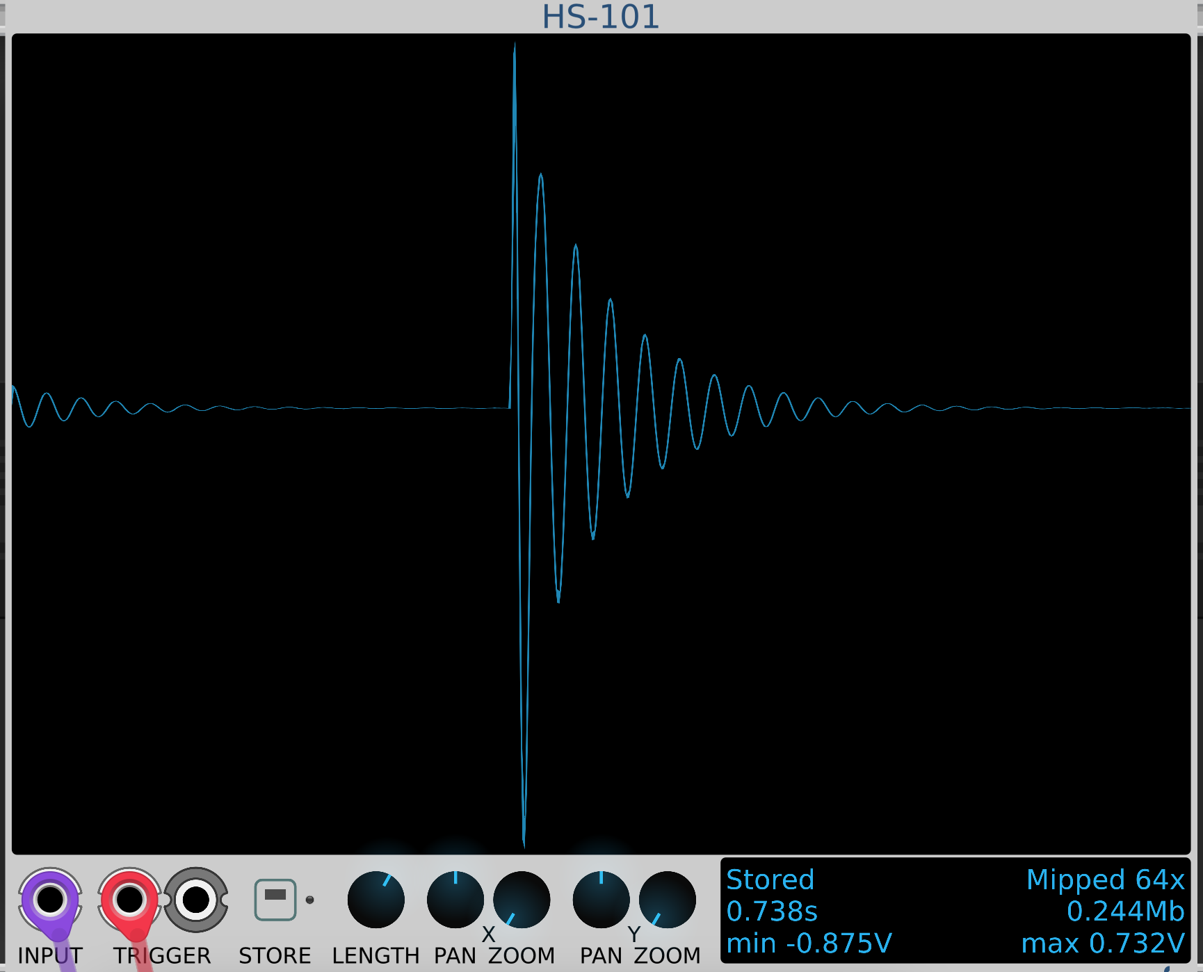
Let's also hear what this sounds like.
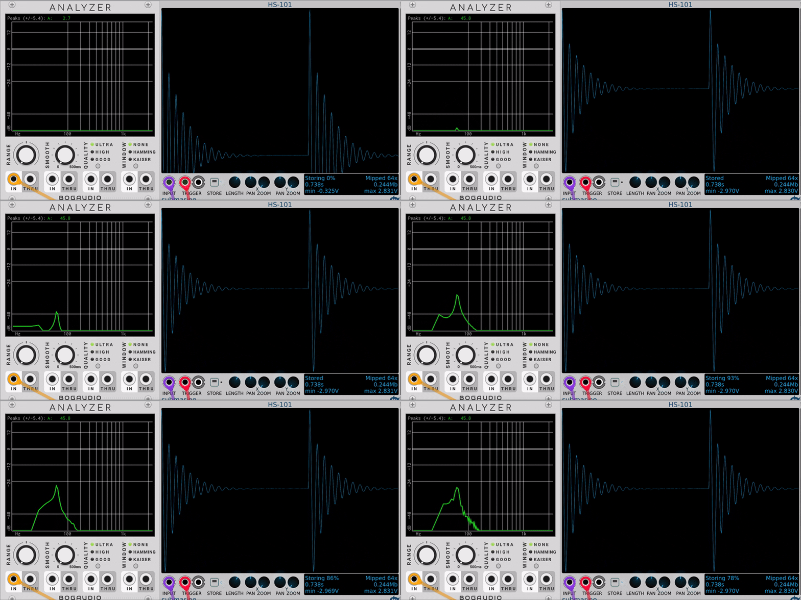
It's quite soft but feels muffled and it's not punchy enough. Compare this to the recoding of the kick drum above, the punch is missing. Look the gif above, there's no energy at the higher inharmonic partials. This is because we have not introduced the pitch shift yet. You might notice that in the waveform the initial first few cycles are packed tightly and slowly the spacing increases. This is because of the transient that rings the filter. The transient is the high energy broadband which starts with a high peak and then dies out instantly. Hence, the filter frequency starts high and slowly decays into silence. This is where that slight pump of the kick comes from. But we can make it more punchy. To do that we apply the same 0 attack minimum decay envelope to the FM input of the filter.
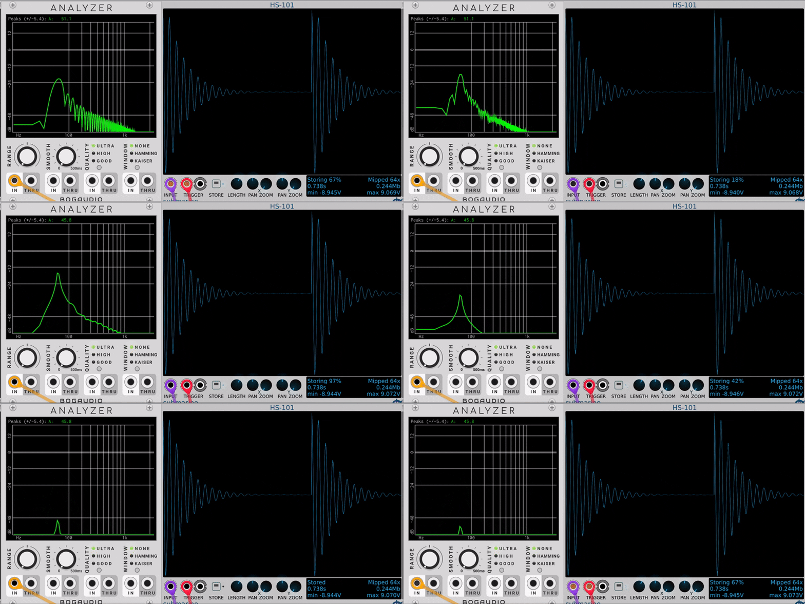
Look at the gif above. There's more energy at the higher inharmonic partials now. Starting from around 2kHz dropping all the way around 100Hz there's an instant energy spike that dies quickly, just like our bass drum membrane's vibrational modes. Now let's hear it.
Sounds much better to me! Much more punchy!
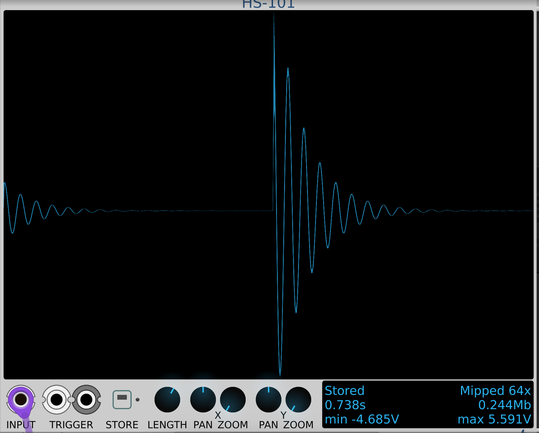
If we compare the two waveforms side by side, we see that the waveform with FM is tighter and has fewer cycles compared to the waveform without FM. But more importantly, look at the min and max voltage of the waveforms. With FM, the pitch envelope drives the cutoff high at the onset. This does three things at once: the resonant is initially much larger ±5V vs ±0.8V; the higher cutoff decays faster, so the ring is shorter with fewer cycles; and as the envelope falls, the cutoff and hence the pitch glides down from a high pitch to the cutoff 50Hz, giving the attack its beater snap. The punch comes from this quickly dying higher inharmonic partials spreading energy from a high pitch to the actual fundamental. For a final touch I am going to apply some EQ to it to shape the sound even further and this is the final result of our excursion.
I like the softness combined with the tight punch of the kick. Almost feels like a basketball bouncing on the floor! Now let's try out the other technique and hear what kick sounds can we get out of it.
Self oscillating filter
In this technique, the resonance is cranked all the way up which reaches unity and the filter starts to self oscillate without any input! Here unity means 1. Resonance is not gain so, the amount of output is proportional to the input but never higher than the input so 1 is the mathematical equivalent of it. So when we turn the resonance all the way up it feeds back 100% of the output to the filter input and it starts to self oscillate. But if there's no input to the filter how can where is it getting the energy to self oscillate? Remember, we are dealing with analog electronic circuits. These circuits have built in noise due to the nature of the components. For a filter like Morgasmatron the noise can come from the following sources:
- Thermal noise: Also known as Johnson-Nyquist noise. The free electrons in the metal conductor are randomly moving throughout the conductor. The reason metals conduct is because of these free electrons. The heat from the environment makes the atoms unstable and that moves the electrons move in random direction. These electrons have momentum, in different directions. Nothing coordinates these electrons so the sum of their random motion is never zero. Precisely, zero is one outcome of many possible answers but rarely it is zero. Think of it this way, if you were to toss a coin 100 times you'd guess that the result will be 50 heads and 50 tails but that is not what happens. The wobble is around ±10 i.e. √100. This is the standard result for a sum of N random events. So at any point because of this movement the electrons create a separation and a separation of charges creates a potential difference i.e. voltage. The metal stays neutral but the charges are separated and that creates a potential difference. This scattering of electrons is random and changes every instant. Randomly wandering voltage is noise. One special characteristic of this noise is that it's white noise which means every frequency in the noise has equal power.
- Flicker noise: Also known as 1/f noise and pink noise. Unlike white noise which has equal power at all frequencies in the spectrum, pink noise dominates at lower frequencies. The relationship is inversely proportional. This noise comes from the imperfections in the semiconductor crystals used in the active electronic components like transistors, transconductance chips, etc. In such crystals there are defect sites which capture the charge carriers from the current flow and eventually release it. So, the current through the device has tiny interruptions. This mainly affects the active electronic components using transistors.
- Noise from power supply: Most power supplies have coils such as transformers and inductors that are used to convert the incoming AC signal to DC. Due to the varying electromagnetic fields the coil can start physically vibrating and introduce noise.
All analog circuits have varying level of noise built into them. An analog oscillator output is never clean as it has built in noise. Look at a sine wave from an analog oscillator and it will not be a pure sine wave of one frequency and will contain some higher harmonics too. This noise is what gave this warmth to the sound. So, even when the there's no input at the filter this noise floor is constantly present in its circuit. A passive filter can only attenuate the signal, chain a bunch of them and you'll see that the output is tiny. This is where active circuits come as they use a device called op amp to add gain to the signal. They also handle the resonance operation. The resonance is a feedback loop via the op amp. So when you have no input to the filter, the noise floor provides the seed for the self oscillating filter. If the cutoff is 50Hz, the filter picks up energy from 50Hz and feeds it to the op amp which adds gain to it. Once the resonance is 100% the circuit hits its limit and the filter starts to self oscillate. The sine wave produced from this self oscillation is never a clean pure sine. Remember, this is an analog circuit which has noise built into it. Not all filters use an op amp though. The classic Moog Ladder filter uses transistors for the gain. The point is for a filter to be resonant it needs an active circuit to add gain. So, crank up the resonance and you filter turns into an oscillator.
So now that we have a self oscillating sine wave, we'll need to gate its output and only open the gate when we want the kick to make its sound and hence we use a VCA to gate the output of the self oscillating filter. We'll need to patch a separate envelope to the VCA to shape the volume of the kick. Remember, the volume decays exponentially so we patch a decaying envelope to the VCA to open the gate. However, there is one difference between the two envelopes for pitch and amplitude. Keeping the amplitude envelope as tight and short as the pitch envelope produces just a click. The pitch shift decays really fast compared to the overall volume of the sound and hence the envelope patched to the VCA will have a longer decay than the pitch envelope. The energy introduced to the membrane is instantaneous and hence the pitch rises and quickly and decays but the membrane still has energy at the lower partials and keeps resonating. This leads to a slower decay of volume compared to the pitch.
So we patch a tight short decay to the FM input of the self oscillating filter for that quick pitch sweep and a longer decay envelope to the VCA to make sure the kick doesn't just sound like a click. Compare this to the method we discussed above. The filter's output is self damping, it doesn't need an exponential envelope to make the decay happen. This time I am applying the FM and VCA envelopes and recording the kick. Let's hear and analyse the resulting kick from this technique.
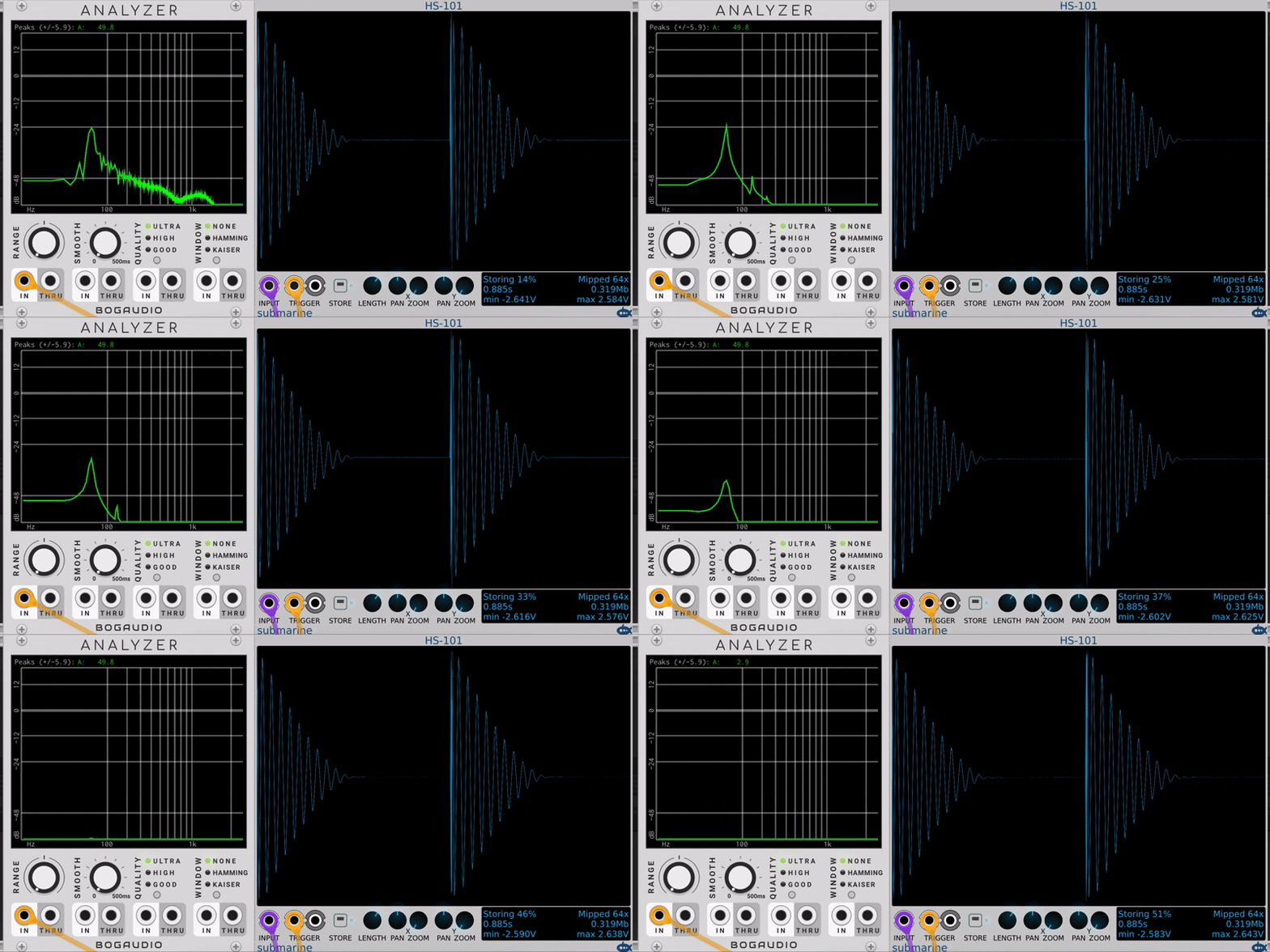
And this is what it sounds like.
This kick is punchy but in my opinion too punchy that it sounds more like a thud than a punch. It has the punch of a 909 kick but is missing its body. Also, if you notice the waveform, it keeps flipping every few kicks and this is one of the flaws that can't be rectified when using a self oscillating filter. Think of it, the filter's output which is constantly emitting a sine wave is patched to a VCA. The VCA is an external multiplier. Without an envelope to the VCA if the outout knob is completely shut, the VCA multiplies the sine output with zero and hence nothing comes out. Now slowly start turning the output knob and based on the knob it will start to multiply the output with a fraction. So let's say the knob is turned upto 50%, the output of the filter is multiplied with 0.5 and you hear low amplitude continuous sine wave. Turn the output knob all the way up 100% and the VCA multiplies the sine wave output by 1 and you hear the sine wave at its highest amplitude. Despite its name Voltage Controlled Amplifier, a VCA is not an amplifier in the traditional sense. The output of a VCA never crosses unity. The output is never more than input. There's no gain in the VCA for it to amplify the signal power more than the power of the input. Whereas, guitar amps amplify the input with respect to its input and make it sound louder than input levels. The reason the waveform flips its phase is because the VCA does not know where in the cycle the sine wave is when the sequencer trigger the envelope with in turn triggers the VCA. So with each new trigger the waveform could be in a completely different phase when the VCA triggers to make the sound and that's what you see in the analyser. This makes each new trigger sound a bit different than the last one. This might not be fully obvious here since the kick is just a simple sine wave.
This can be easily rectified with a Voltage Controlled Oscillator (VCO) since most of them have a sync input which can be used to sync its cycle to let's say a sequencer which triggers the envelope. So patching the same sequencer output to the oscillator's sync input and every time the kick triggers the oscillator drops the current cycle and starts again. This makes sure that with every trigger the kick sounds the same. But since I am using a filter which has none such sync capability.
So back to the kick. Now to make the sound a bit more full I can use the filter's Q-Drive which drives the resonance and adds more harmonics to the sine wave. I can also apply some EQ to the kick. Here is what is sounds with Q-Drive close to 80% without distorting the wave and the same EQ as used above with the kick from the previous technique.
This has a bit more body to it and has a solid punch. EQing the kick is something that needs to be as per taste and based on the track/mix that you're doing. The kicks I have synthesised here are not part of any tracks so I am just applying EQ to taste without thinking of how the sound might fix in a mix.
Closing thoughts
If you might have noticed, I did not layer the click noise at the start of the sound. Honestly, in my exploration, I did layer the click however it did not do much to the initial transient of the kick. I have a noise source in my rack and high passed the noise, patched to a VCA to make it sound like a click and mixed it with my kick. This however did not bring a big change to the sound of my kick.
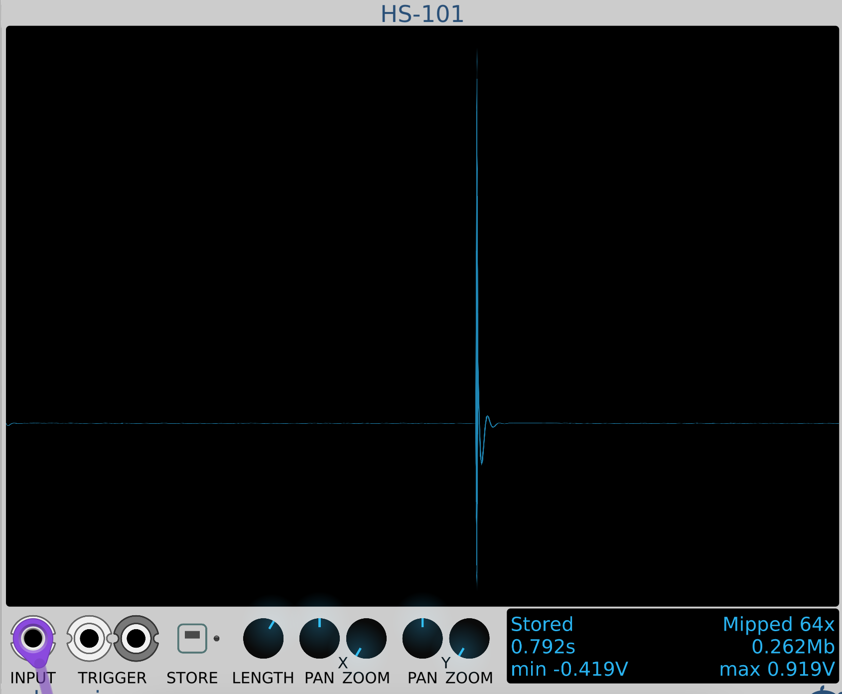
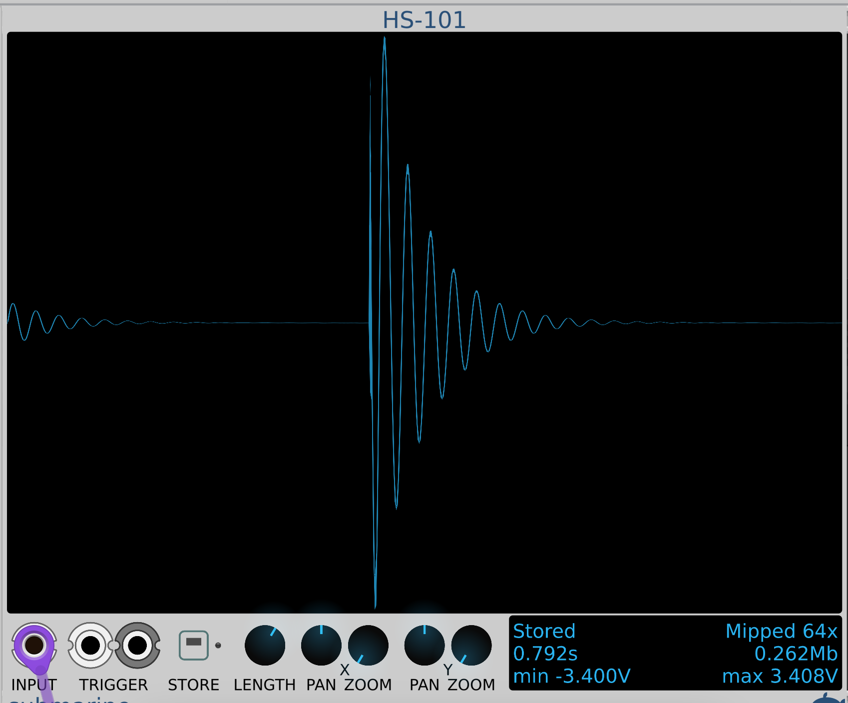
Let's hear it without and with the click.
The noise click is clearly audible and since noise is stochastic its energy varies on every trigger. This sort of ties to how a natural kick drum sounds since it's a human playing it every kick sounds different in a way. Also, adding this noise helps with playback on speakers which can't reproduce the low ends properly so the noise acts like a kick and cuts through the track on low quality speakers. But for now I am skipping the noise click for my kicks. I have a multiband saturator which can be used to saturate or overdrive the lows, the mids, and the highs separately of the same input signal. So I can add saturation in the highs for that noise click sound 2-3kHz that will be not stochastic in nature since the click comes from the kick and not an external signal. But this is new module that I got and I haven't explored it fully. Maybe once I explore it with different sounds I can come back here and add the saturated kicks.