Making a simple 8 step sequencer Published: 20th January 2025
I bought my first ever synthesiser a couple of months ago and have
been playing around with synthesising sounds learning the basics of
sound design. To have some structure in my research and learning I
started with synthesising percussive sounds like kick drums,
cymbals, hi-hats, etc. Synthesising a kick drum sound is one thing
but adding movement to the sound on its own a separate technique
which is not really possible with my Moog Mavis.
Moog Mavis is a perfect synth to learn the basics of sound
synthesis. It is a semi modular synth packed with a lot features
like its VCO with pulse width modulation, waveform mixing, 24dB Low
Pass Filter, audio rate LFO (which can act as a second VCO), 24
point patch bay which helps extend the base functions to a greater
extent, 4 stage (ADSR) envelope generator, wavefolding circuit,
allowing for additive synthesis, patchable sample and hold circuit
etc. It does lack certain capabilities like a noise source,
sequencer, modifying the slope of the filter, fewer modulation
options, etc. But given the price of the Mavis it does pack a lot of
functionalities and is an excellent synth for getting into sound
synthesis.
Mavis primarily uses subtractive synthesis to generate sounds and I
was able to generate kick drum sounds by skipping the primary VCO
and using LFO as the source of my sound and using the attenuator to
controls how much the envelope affects the pitch with some extra
processing like compression on Ableton but not having an ability to
trigger the sound on its own limits the exploration I can do in
designing the sound.
In comes the sequencer. But first what is a sequencer anyway?
In sound synthesis we have oscillators, filters, amplifiers that
create and shape the sound. These modules give us the ability to
craft the timbre of the sound but to create music out of the sound
we need to control when the sound starts and stops. Music is just
organised sound. In the musical structure sounds start, repeat, and
stop and start again. We also need a way to program in what pitch to
play and how they change over time. A sequencer helps us program
these attributes of a sound. Sequencers tell the synthesiser modules
when to trigger sounds and what parameters to change for that
trigger. The most basic way a sequencer helps in synthesis is
through gate signals. A gate signal acts like an on/off switch. It
is one of the main signal types that are passed around in modular
synthesisers. It jumps to high level which is typically 5 volts when
a sequencer jumps to the next step in the sequence. When a gate
signal is applied to an envelope generator, the start of the gate
tells the envelope to go through its stages Attack and Decay, while
the gate stays high the envelope stays in its Sustain stage and when
the gate is low the envelope moves to the Release stage. Beyond this
sequencers can also help control other parameters of the sound.
While one sequence controls the sound trigger through envelope
generators other sequence can control the pitch of the sound and
another can control the cutoff filter through something called
Control Voltage (CV). So sequencers play a crucial role in defining
the overall sound coming out of a synthesiser and adding a movement
to it.
Moog Mavis does not come with a sequencer. Moog has other synths like its DFAM (drum machine), Mother 32 which come with their own sequencers built into the machines. But we are in the world of modular synthesis. There is a reason it is called modular and that gives endless possibilities to explore. We can build our modules and hook into our modular synthesiser setup. But how do we even create a sequencer? Do we get small resistors, transistors, capacitors, breadboards and bunch of wires to make a sequencer circuit? Of course we can.
Though I have studied electronics in my year 11, 12, and first year
of engineering I am more of a software engineer than an electrical
engineer so I found a way to do less electronics and more
programming to build my step sequencer.
Electro Smith makes hardware and software tools for audio
applications. They are particularly known for their creating the
Daisy platform which has become an important tool in modern DIY
audio electronics community. Their flagship product, the Daisy, is a
powerful microcomputer platform specifically designed for audio
applications. Think of it as a specialized "brain" for audio devices
it's like having a tiny but powerful music computer that can be
programmed to process and generate sound in various ways. Daisy
supports a number of languages including C++, Arduino, and Max/MSP,
etc. to program audio on it.
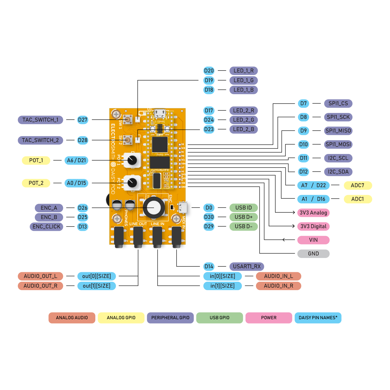
This is Electro Smith Daisy Pod. It takes the daisy microprocessor
and adds a set of physical controls and connections like LEDs,
switch buttons, knobs, etc. to quickly get started with audio
programming.
So here is my setup for a simple 8 step sequencer which for now only sends a gate output using a daisy pod:
- Use the encoder to step through each step in the sequence
- Press the encoder to enter or leave edit mode
- Once in edit mode use the switch number 2 to turn on/off a step in the sequence
- For every on step in the sequence LED 2 turns green
- LED 1 shows 8 different colours for each step in the sequence
- Use knob 1 to change the tempo of the step
Here is the simple c++ method running on Daisy Pod to generate a gate signal for steps in a sequence:
constexpr uint8_t NUM_STEPS = 8;
constexpr float MIN_TEMPO = 100;
constexpr float MAX_TEMPO = 400;

enum Mode
{
    STEP_EDIT,
    GATE_VIEW
};

struct
{
    uint8_t currentStep;
    uint8_t editStep;
    bool active[NUM_STEPS];
    float phase;
    float tempo;
    Mode mode;
    bool gateState;
} sequencer;

Color stepColors[NUM_STEPS];

void updateLeds()
{
    // edit mode: show selected step
    if (sequencer.mode == STEP_EDIT)
    {
        hw.led1.SetColor(stepColors[sequencer.editStep]);
        if (sequencer.active[sequencer.editStep])
        {
            hw.led2.Set(0, 1, 0); // Green
        }
        else
        {
            hw.led2.Set(0, 0, 0); // Off
        }
    }
    // play mode: show active step + gate state
    else
    {
        hw.led1.SetColor(stepColors[sequencer.currentStep]);
        // led2 shows gate state (green when active)
        if (sequencer.gateState)
        {
            hw.led2.Set(0, 1, 0); // Green
        }
        else
        {
            hw.led2.Set(0, 0, 0); // Off
        }
    }
    hw.UpdateLeds();
}

void AudioCallback(AudioHandle::InputBuffer in, AudioHandle::OutputBuffer out, size_t size)
{
    hw.ProcessAllControls();
    sequencer.tempo = MIN_TEMPO + hw.knob1.Process() * MAX_TEMPO;

    if (hw.encoder.RisingEdge())
    {
        sequencer.mode = sequencer.mode == STEP_EDIT ? GATE_VIEW : STEP_EDIT;
        updateLeds();
    }

    if (sequencer.mode == STEP_EDIT)
    {
        int32_t inc = hw.encoder.Increment();
        if (inc != 0)
        {
            sequencer.editStep = (sequencer.editStep + inc + NUM_STEPS) % NUM_STEPS;
            updateLeds();
        }
    }

    if (hw.button2.RisingEdge() && sequencer.mode == STEP_EDIT)
    {
        sequencer.active[sequencer.editStep] = !sequencer.active[sequencer.editStep];
        updateLeds();
    }

    /**
     * when we say tempo is 120BPM each beat represent a quarter note
     * in most electronic music and hence sequencers steps need to align with eighth note
     * let's say the tempo is 120
     * tempo/60 = 2 beats per second
     * then 2/2 makes each beat take eight of a note
     * without the last division /2 each step would last a full beat i.e. a quarter note
     */
    float phaseInc = (sequencer.tempo / 60.0f / 2.0f) / hw.AudioSampleRate();

    for (size_t i = 0; i < size; i++)
    {
        sequencer.phase += phaseInc;

        if (sequencer.phase >= 1.0f)
        {
            sequencer.phase -= 1.0f;
            sequencer.currentStep = (sequencer.currentStep + 1) % NUM_STEPS;
            sequencer.gateState = sequencer.active[sequencer.currentStep];

            // Update LEDs only when step changes in view mode
            if (sequencer.mode == GATE_VIEW)
            {
                updateLeds();
            }
        }

        // create a gate pulse that stays high for 50% of the step duration
        // this ensures a clear rising edge at the start of each active step
        float gateThreshold = 0.5f; // 50% duty cycle
        bool trigger = (sequencer.phase < gateThreshold) && sequencer.gateState;
        out[0][i] = out[1][i] = trigger ? 0.95f : -0.95f;
    }
}
Tempo refers to the overall speed or pace of the sound/music. If you were to tap your foot to the music it's how fast or slow these regular movements would be. Tempo is measures in Beats Per Minute (BPM). Each beat represents a quarter not and this comes from western classical music notation where the quarter note is considered the basic unit of time. When you say "1-2-3-4" to keep time, each number typically represents a quarter note. However in most modern electronic music the most common rhythmic subdivision is the eighth note. This is because:
- Most electronic drum patterns are built around a fundamental rhythm called the "sixteenth note grid," where a 4/4 bar is divided into 16 equal parts. The kick drum often falls on quarter notes (beats 1-2-3-4), while the hi-hats typically play eighth notes (the "and" between each beat). This creates the characteristic "boom-tss-boom-tss" pattern heard in electronic music.
- When you hear a basic house music pattern, what feels like the basic "pulse" is usually happening at the eighth note level. The iconic electronic music rhythm:
- Kick on the quarter notes (1-2-3-4)
- Open hi-hat on the eighth notes between (the "and" counts)
- Snare/clap on beats 2 and 4
So when we make a step sequencer with 8 steps, having each step represent an eighth note means:
- One complete sequence = 4 quarter notes = 1 bar of music
- Each step = 1/8 of the bar = eighth note
This is an important piece of conversion we need to make in our code
to correctly calculate the tempo and the length of each step for
that tempo.
To calculate the frequency of each step we divide the current tempo
by 60 to convert BPM to beats per second and divide by 2 again
because without the last division each step would last a full beat
i.e. a quarter note.
Now that we know how long is each step, let's emit a gate signal for each active step in the sequence. Moog Mavis Gate input works with the Eurorack modular voltage levels and audio interface voltage levels. In a Eurorack system, gate signals typically swing between -5V and +5V or even up to +8V. However, the Mavis is more flexible - it can also work with the lower voltage levels that come from audio interfaces.
Daisy Pod works with an audio sample rate of 48kHz. In each audio
sample the phase increases by
1.0 / 48000 = 0.0000208333...
The phase variable acts like a musical metronome that counts from 0
to 1. When it reaches 1, several things happen:
- The phase resets back to 0 (phase -= 1.0f)
- The sequencer moves to the next step: sequencer.currentStep = (sequencer.currentStep + 1) % NUM_STEPS;
- The gate output updates based on whether the new step is active
During each step, phase goes from 0 to 1. Checking if phase is below
0.5 essentially divides each step into two equal parts. Think of it
like splitting a musical note into its "pressed" and "released"
states and when it's below 0.5, the gate is high (if that step is
active). This creates a perfect 50% duty cycle meaning the gate
signal is high for exactly half of each step's duration.
At 120 BPM, here's what happens in real time:
- Each beat represents a quarter note
- One beat takes 0.5 seconds (60 seconds / 120 beats = 0.5 seconds per beat)
- The division by 2 means each step represents an eighth note, not a quarter note.
- At 120 BPM, each eighth note (step) takes 0.25 seconds (half of a quarter note)
- For each step Gate is high for 0.125 seconds (half of 0.25) and Gate is low for 0.125 seconds
- sequence has 8 steps, so one complete sequence takes: 8 steps × 0.25 seconds = 2 seconds total
In musical terms, if we are in 4/4 time (the most common time signature), this means:
- Each bar (measure) contains 4 quarter notes or 8 eighth notes
- Your 8-step sequence exactly fills one bar of music
- Every 2 seconds, the sequence completes one full bar
By using phase this way is it creates perfectly timed transitions
regardless of the tempo. Whether you are running at 40 BPM or 340
BPM the phase accumulation automatically adjusts to keep everything
in sync with your audio rate, preventing any timing jitter that
could affect the rhythmic precision.
Once we know when to output a signal based on the phase we output a
voltage of +0.95V and -0.95V. In digital audio systems like your
Daisy Pod, there is a concept called "headroom" - a small safety
margin below the absolute maximum voltage the system can handle. The
maximum theoretical voltage range in most audio systems is ±1.0
volt, but using exactly ±1.0 could cause problems.
First, using 0.95 provides a small buffer against clipping.
Digital-to-analog converters (DACs) can behave unpredictably when
pushed to their absolute limits. They might introduce distortion or
fail to reach the exact maximum voltage consistently. By staying
slightly below the maximum, you ensure the signal remains clean and
reliable.
Second, real-world electronic components have manufacturing
tolerances and slight variations. The 5% headroom (the difference
between 0.95 and 1.0) helps accommodate these variations. It's like
leaving a little extra space when parking your car - it's better to
have a small margin of safety than to risk bumping into something.
Third, when signals pass through multiple stages of audio equipment
(like from my Daisy Pod to the Mavis), each stage might introduce
tiny amounts of gain or amplification. If I started at exactly ±1.0V
and any stage added even a tiny bit of gain, I would get clipping.
Starting at ±0.95V gives the signal room to breathe through the
entire signal chain.
This gives a simple step sequencer which outputs a gate signal for
each active step in the sequence. Next I'll be adding the
functionality to output a pitch CV to change the pitch of each
active step in the sequence.
Article coming soon...